The DM805-AI featured in supporting 0-5V analogue signal for speed controls. Like other DM series drives, it brings a unique level of system smoothness, providing optimum torque and nulls mid-range instability. The self-test and auto-configuration technology offers optimum responses with different motors and easy-to-use. The driven motors can run with much smaller noise, lower heating, smoother movement than most of the drivers on the markets. Its unique features make the DM805-AI an ideal solution for applications that require low-speed smoothness.
Not only implemented in traditional stepper systems for positioning controls, the DM805-AI has also been adopted in OEM applications for speed controls. In many applicaitons, Leadshine clients successfully implemented DM805-AI for speed controls, especially in low-speed applications to replace brushless DC motors plus planetary gearboxes.
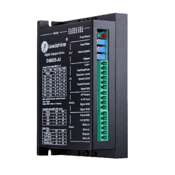
The three built-in potentiometers are used to preset and adjust the velocity, acceleration and deceleration. In 0-5V speed mode, the motor speed is controllable and follows the analogue 0-5V input. In high/low speed mode, the motor speed is selected by digital input and adjusted by the high/low speed potentiometers. The user can run the motor with the least configuration and connection. In position mode, the DM805-AI is a traditional stepper drive. There is a 5V power supply output for customer use.
Features
Extra-low motor noise offers excellent quietness
Analogue signal (0-5V) for speed control
Step & direction control signals also acceptable
Internal step generator for no motion controller system
Built-in 5V output for an analogue control and testing
Built-in potentiometers for speed, acceleration and deceleration adjusting
Limit signal input for safe operation
Anti-resonance and low-speed ripple smoothing
Supply voltage up to 80 VDC
Output current programmable, from 0.5A to 7.0A
Electrical Specifications
Parameter
Min
Typical
Max
Unit
Input Voltage
18
60
80
VDC
Pulse Input Frequency
0
-
200
kHz
Logic Signal Current
7
10
16
mA
Isolation Resistance
500
-
-
MΩ
Velocity Control
Item
Specification
Dead Band
Resolution
Min
Max
Analogue Input
0-5V Speed Mode
0-5 V
10 mV
10 mV
0 Rev/s
25 ± 0.5 Rev/s
External POT Mode
20 mV
Accel / Decel / Ramp Potentiometer
0-25 turns
10 mV
10 mV
0.5 Rev/s2
250 ± 1Rev/s2
LoSpeed Potentiometer
0-25 turns
10 mV
10 mV
0 Rev/s
5 ± 0.01Rev/s
HiSpeed Potentiometer
0-25 turns
10 mV
10 mV
0 Rev/s
25 ± 0.5 Rev/s
Operating Environment
Cooling
Natural Cooling or Forced cooling
Operating Environment
Environment
Avoid dust, oil fog and corrosive gases
Storage Temperature
-20 °C - 65 °C (-4°F - 149 °F )
Ambient Temperature
0°C- 50 °C (32 °F- 122°F)
Humidity
40%RH - 90%RH
Operating Temperature (Heat Sink)
70 °C (158 °F) Max
Vibration
10-55Hz, 0.15mm/s
Storage Temperature
-20 °C- 65 °C (-4 °F- 149 °F )
Digital I/O Signal Connector
6-pin screw terminal, 3.81 mm space
Pin
Name
I/O
Description
1
COM+
Power
+5V Power Input, common reference of all inputs
2
Run/Stop/Pulse
I
Run/Stop signal for 0-5V analogue, Lo/Hi Speed and External POT mode. In Pulse/Direction mode, it accepts pulse input.
3
Direction / +Limit
I
Direction input for 0-5V analogue, Lo/Hi Speed and Pulse/Direction mode. It is the +limit switch input in External POT mode. When +Limit is activated, the motor speed decelerates to zero in the acceleration set by Ramp potentiometer. The +Limit is only activated when the voltage applied to 0-5V input is 2.5-5V.
4
Speed / (-)Limit
I
Speed selection input in Lo/Hi speed mode. It is the -limit switch input in External POT and 0-5V Speed mode. When +Limit is activated, the motor speed decelerates to zero in the acceleration set by Ramp potentiometer. In External POT mode, the –Limit is activated only when the voltage applied to 0-5V input is 0-2.5V. In 0-5V speed mode, the –Limit is activated only when Direction input is connected to Signal GND.
5
Enable / Disable
I
This signal is used to enable or disable the power stage. Usually left it unconnected to enable the power stage.
6
Signal GND
GND
Signal ground. It is common with the power ground.
Analogue Signal Connector
4-pin screw terminal, 3.81 mm space
Pin
Name
I/O
Description
1
+5V Output
O
+5V Power Output, reference to signal ground
2
0-5V Input
I
Analogue 0-5V reference input
3
Signal GND
GND
Signal ground. It is common with the power ground.
4
Signal GND
GND
Signal ground. It is common with the power ground.
Power Connector
6-pin screw terminal, 3.81 mm space
Pin
Name
I/O
Description
1
Power GND
GND
Power ground
2
+20-80VDC
I
Power supply input, 24-72VDC recommended, leaving rooms for voltage fluctuation and back-EMF.