Frequently Asked Questions
Technical Support
- Kinco Servo Drive Support
- How to Configure Your Kinco Servo Tool for Optimal Performance- A Step-by-Step Guide
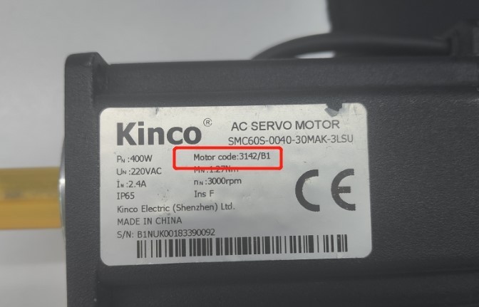
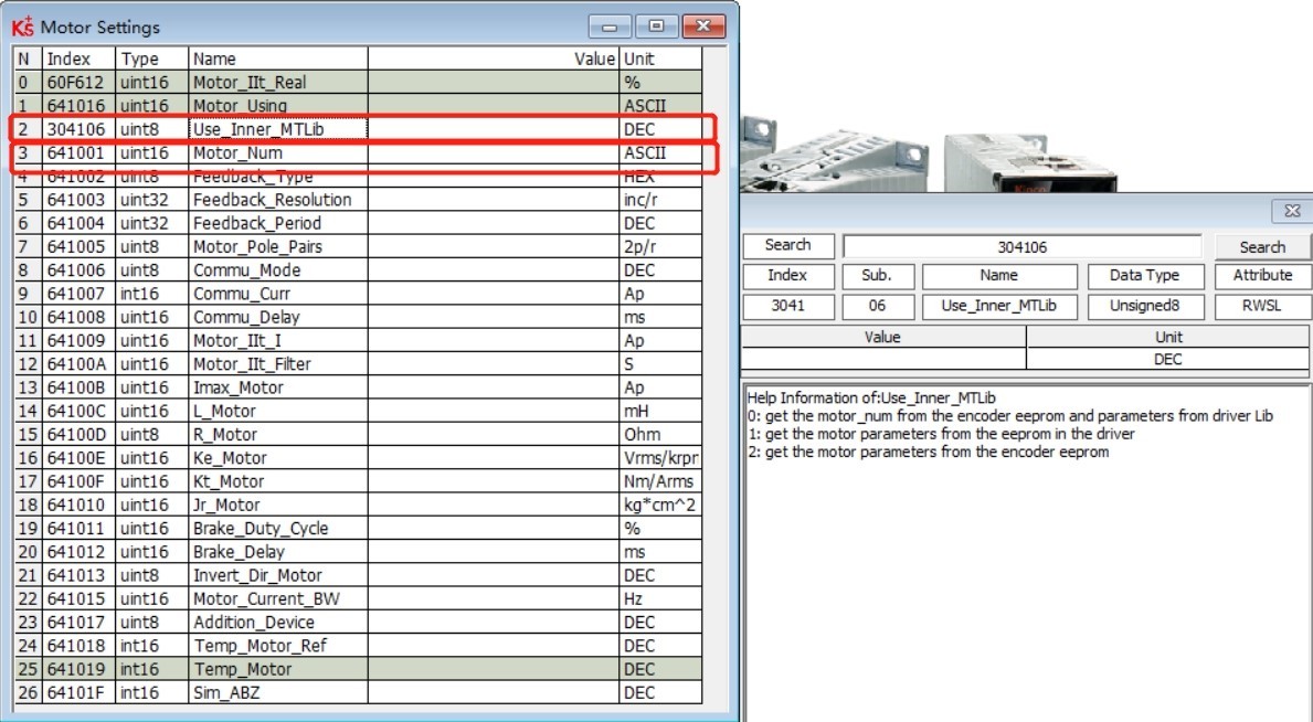
- Kinco Servo Drive does not automatically recognise a Kinco motor.
If the drive does not recognise itself automatically you need to change the Use_Inner_MTLib to 1 and then enter the motor code on the motor nameplate.
- Kinco Servo Drive operation mode is stuck in -4.
The Operation Mode is set in the basic Operation screen.
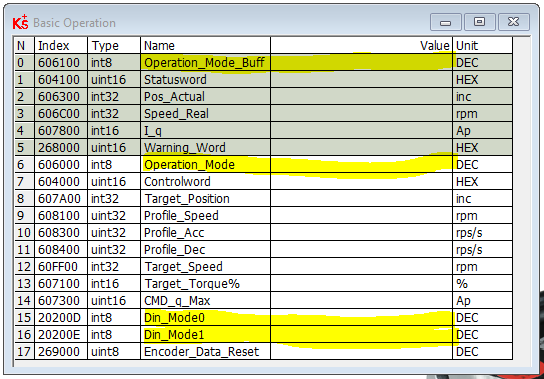
- The Operation mode that is currently set is displayed in 60600 Operation Mode. The operation Mode Buff 606100 is the mode that is being executed when the motor is energised.
- Din Mode 0 and Din Mode 1 can be set with specific operation modes that you wish to run and you can switch between them by using the state of a digital input.
- The default value for Din mode 0 is -4 and for Din Mode 1 is -3. If the associated input is at state 0 then the mode of operation will be -4 if the state of the input is 1 then the operation mode will be -3.
- If no input is set the operation mode will be at its default which is -4. Although you can change it in software and run the system live with a different operation mode when you power off it will revert to -4.
- If you are only going to use one mode for example 1 position mode then set Din Mode 0 to 1 and then set the digital IO Din(x) to operation mode select.
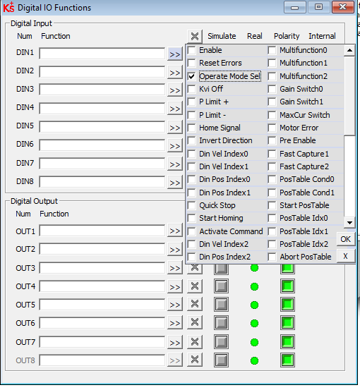
- If you are just using that mode then you never have to wire the digital input. The very fact that it is set and at state 0 will force the operation mode to 1.
- If you do however wish to change between modes such as position and torque then you will need to set Din mode 0 and Din mode 1 and assign the digital input to operation mode select and wire it so that the state change will cause the drive to change between modes.
- Note: in the default setting for the drive the default operation mode -4 causes a number of inputs to be populated automatically. Din 3 is assigned as operation mode select. So just change Din Mode 0 should cause the operation mode to be selected.
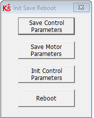
- Please remember that the settings must be saved in the drive using the save control parameters before powering off.
- How to Configure Your Kinco Servo Tool for Optimal Performance- A Step-by-Step Guide
- CS Labs Motion Controller Support Page
- E-PID fault when using CSMIO/IP controllers and Mach3/Mach4 control software. Reasons and advice.
The E-PID fault is caused by a significant difference between a control software set position and an actual position of a motion controller.
It is generated by low-level motion controller safety algorithms when:
1. Control software failure.
In this situation, it is recommended to reinstall the control software.The situation is very rare, but you should take it into account, especially in the case of Mach3 CNC software.2. The configuration file of the control software has been corrupted.In this situation, it is recommended to reinstall the control software and configure it manually. The situation is very rare, but you should take it into account, especially in the case of Mach3 software.3. Control software mistake in generating trajectory.4. Unknown plugins or language-changing packages installed in the control software.The situation concerns Mach3.5. In the case of CSMIO/IP-A controllers there are problems with:a) feedback,b) a servo drive (servo driver + servo motor),c) tuning of position PID regulator of the controller,d) tuning of velocity PID regulator of a servo drive.6. Strong network transmission interference, leading to controller’s data buffer exhaustion, which may cause jerks in machine work.7. A computer network card or computer has energy-saving modes that affect the stability of the network connection.8. A low-quality power supply, which cannot work in industrial conditions, was used to power the motion controller.9. No motion controller support for some (mostly little-used) functions of the control software.It happens in the case of Mach3 and Mach4, due to specific solutions used in this software, the functions will never or not in the nearest future be supported by CSMIO motion controllers.Mach3 – It is not recommended to use the G31 command in Mach3 versions newer than 03.043.044.The older versions allow G31 to be used only from the macro level.Mach4 – This software is continuously developed as well as the CS-LAB plugin, therefore the situation may change dynamically.SimCNC – This control software does not encounter this problem as the control software and firmware of the CSMIO motion controller controllers are created by the same developers.10. The CSMIO/IP-S or CSMIO/IP-A motion controller was damaged.The situation is theoretically possible and should be considered last. - Connection of THC with simCNC (THC Analog Smart, THC Digital)
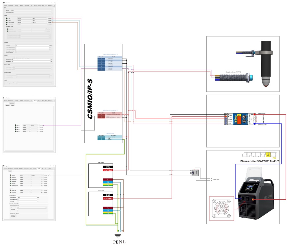
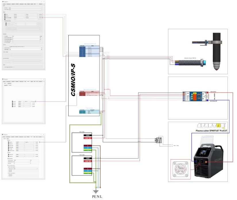
1. THC Digital
The diagram applies to a situation where a plasma generator does not have a dedicated analog output
0-10V with a voltage divider and a digital output confirming the presence of an electric arc. In this situation, an external torch height control should be used. The diagram includes:– connection with an inductive sensor for measuring the height of a sheet metal.
– connection of an external sheet height controller (PROMA).
– connection of a plasma generator (SPARTUS).Open the PDF file for larger drawing details
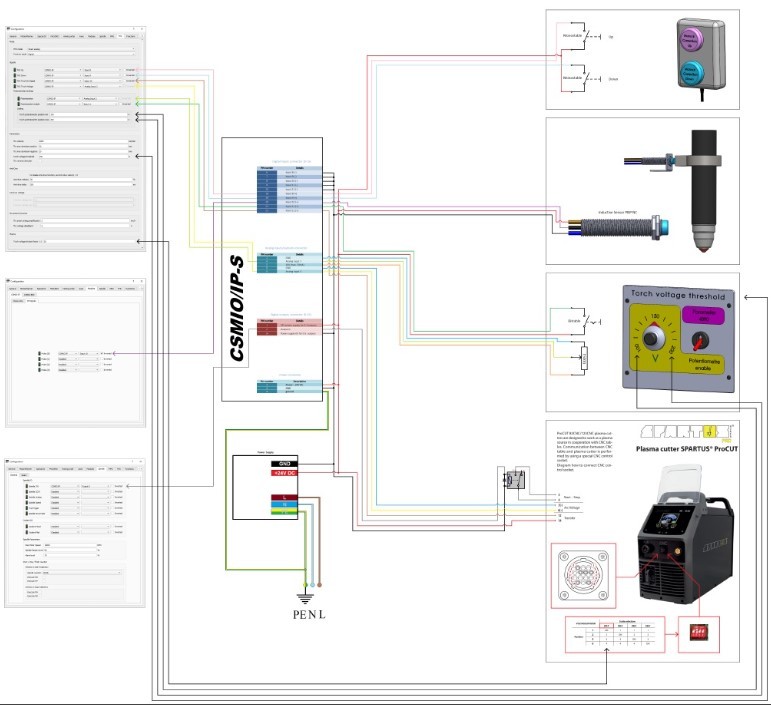
2. THC Analog Smart
The diagram applies to the situation where a plasma generator has a dedicated 0-10V analog output with a voltage divider and a digital output confirms the presence of an electric arc. In this situation, an external torch height controller is not required to start the automatic torch control, because a CSMIO/IP controller and simCNC software fully replace it, and even guarantee better precision and dynamics of the torch height adjustment. The diagram includes:
– connection of a manual manipulator for temporary manual correction of the torch height.
– connection with an inductive sensor for measuring the height of a sheet metal.
– connection of an operator panel, equipped with a potentiometer for setting an arc voltage, along with a switch that allows the selection of the arc voltage setting through the potentiometer or a digital value from the simCNC screen (parameter 4090)
– connection of a plasma generator (SPARTUS) using the full capabilities of the CNC socket.Open the PDF file for larger drawing details
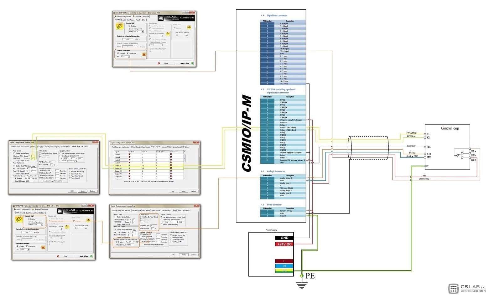
- Connection drawing of CSMIO/IP-M ~ Kinco FV100 VFD
Click to enlage
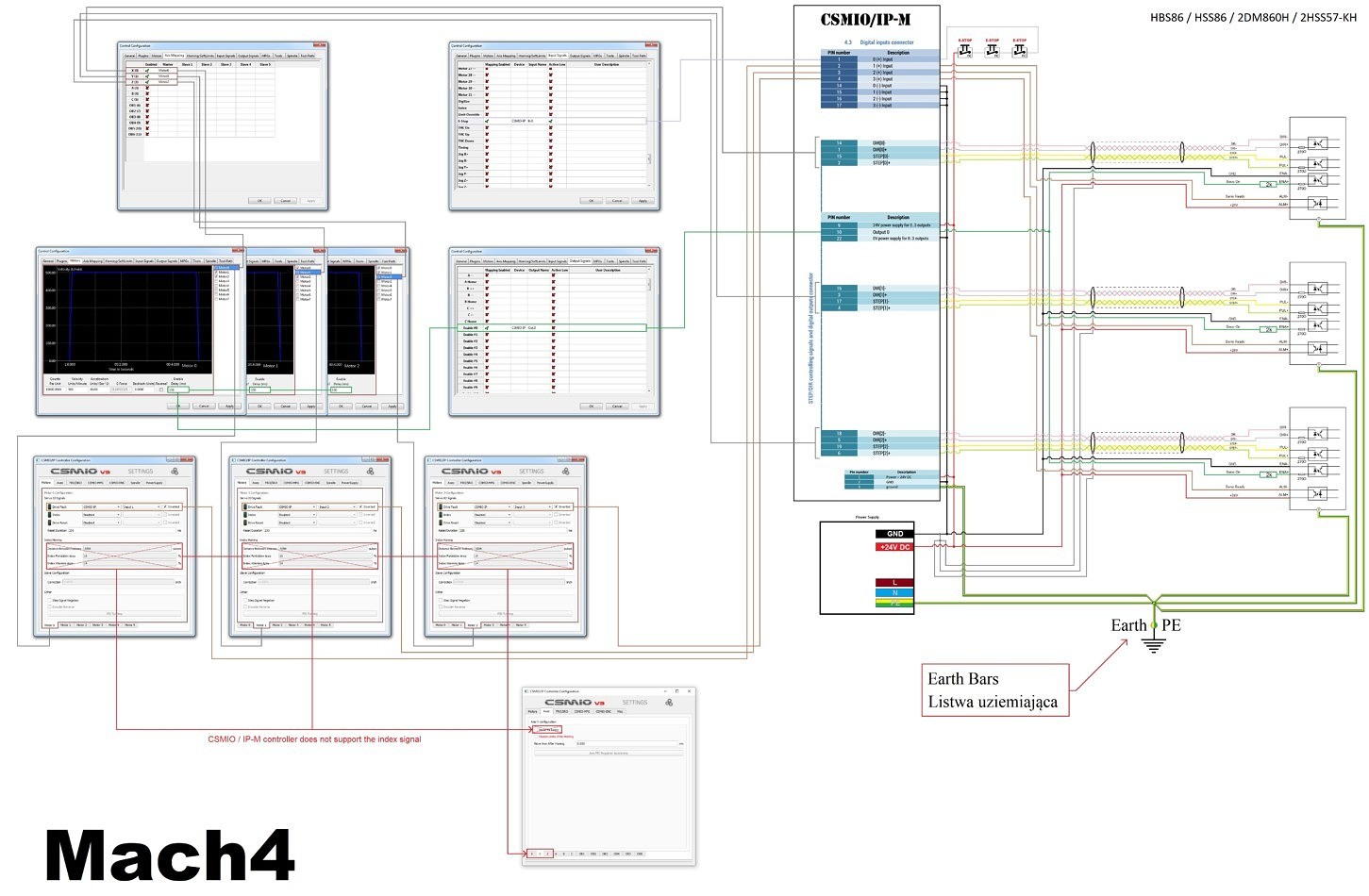
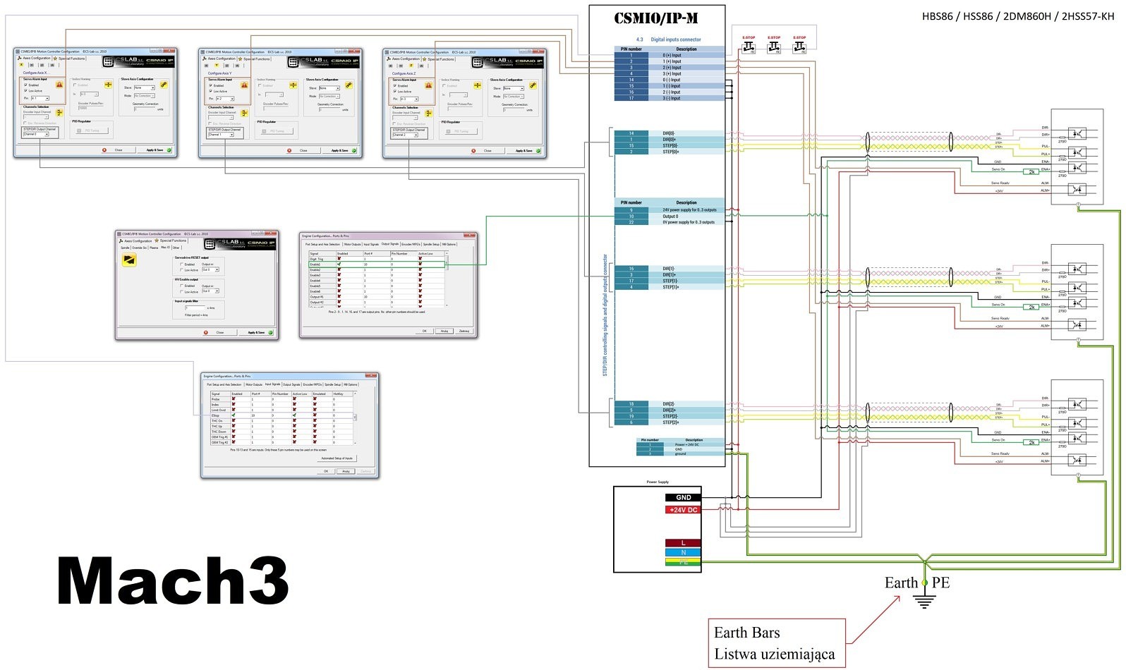
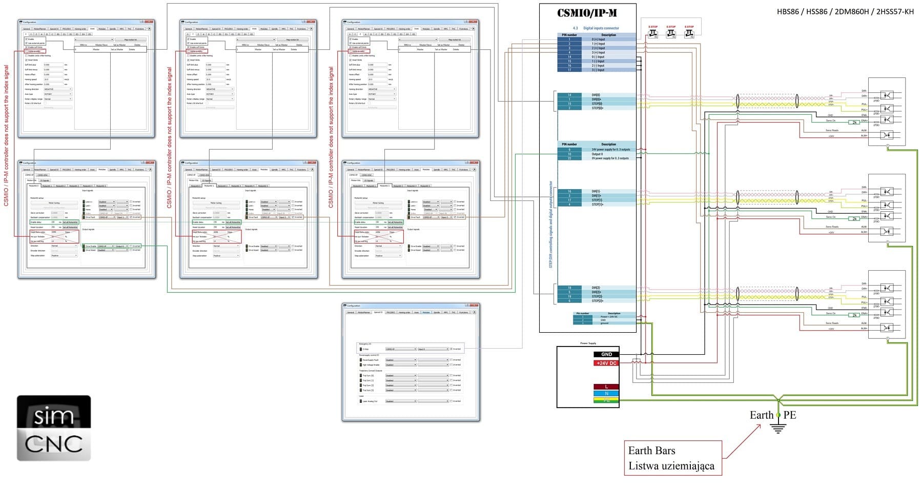
- Connection of CSMIO/IP-M controller with stepper drives HBS86, HSS86, 2DM860H, 2HSS57-KH (simCNC, Mach3, Mach4)
We publish new schemes. This time it will help you to connect the CSMIO/IP-M controller and the stepper drives.
1. Connection of CSMIO/IP-S controller with Leadshine CS-D stepper drives (simCNC)
(Click to Enlarge)
2. Connection of CSMIO/IP-M controller with Leadshine CS-D stepper drives (Mach3)
(Click to Enlarge)

3. Connection of CSMIO/IP-M controller with Leadshine CS-D stepper drives (Mach4)
(Click to Enlarge)
- Kinco CD2 series driver and CSMIO/IP-A Connection Diagram
Driver Enable, Fault, Reset, Ready (…) signals connection scheme of KINCO CD2 driver series.
(Click to Enlarge)
- how do I connect the FV2 AC inverter to the CSMIO-IP/S or A and configure SIMCNC.
You have to configure the VFD settings responsible for the X1, X2, AI1, R1b and R1c .
- E-PID fault when using CSMIO/IP controllers and Mach3/Mach4 control software. Reasons and advice.
- Leadshine Stepper / Servo Support
- Kinco Servo Drive Support
Customer Service
- What is our company VAT number?
Our VAT number is GB651281648
- Does Motion Control Products have any certifications?
Motion Control Products Ltd is ISO9001 and Joscar certified.
- What is our privacy policy?
You can view our privacy policy here.
- How do i return my order?
You may read our return policy here.
- What is our company VAT number?