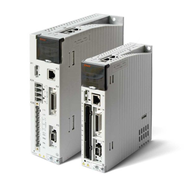
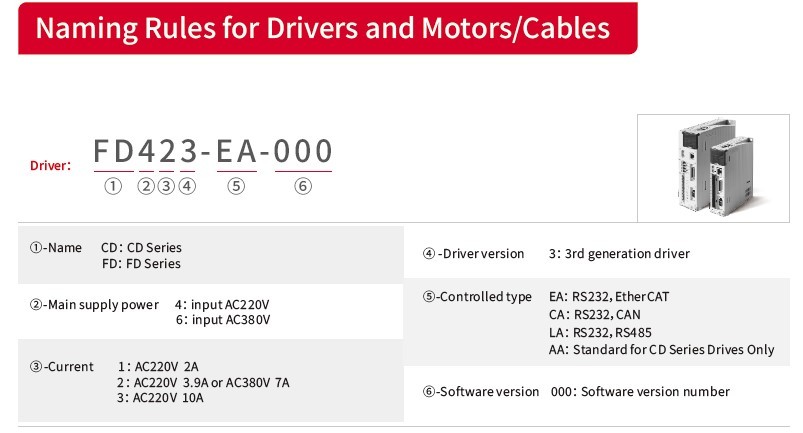
| Model Parameters | CD413-AA-000 | CD423-AA-000 | CD433-AA-000 | CD623-AA-000 |
| Main Supply Voltage | 1PH,AC220V +/-10% 50/60Hz+/-3Hz (750W / 7A - 200W / 3A) | 1PH,3PH,AC220V +/-10% 50/60Hz (14A) | 3PH,AC380V -415VAC 50/60Hz (12A) |
| Control Circuit Voltage | 200-240VAC±10%, 50/60Hz±3Hz, 0.5A |
| Max Continuous Current | 2A | 3.9A | 10A | 7A |
| Peak Current (PEAK) | 7A | 15A | 27.5A | 25A |
| Feedback Signals | Single and Multi-Turn Encoder |
| Brake chopper | CD413,CD423 Built-in braking resistor 100 Ω, limiting power 10 W;CD433 Built-in braking resistor 100 Ω, limiting power 20 W; CD623 Built-in
braking resistor 300 Ω, limiting power 20 W; If the actual power exceeds 10W, an external braking resistor is required. |
| Brake chopper threshold | DC380V±5V | DC680V±5V |
| Over-voltage alarming threshold | DC400V±5V | DC700V±5V |
| Under-voltage alarming threshold | DC200V±5V | DC400V±5V |
| Cooling method | Natural air cooling | Fan |
| Weight (Kg) | 0.8 | 1.33 |
Position Mode | Maximum frequency of input pulse | Differential transmission mode: up to 4MHz, open collector transmission mode: 500KHz |
| Pulse command mode | Pulse+direction, CCW + CW, A+B Phase( 5V - 24V ) |
| Command smoothing | Low-pass filtering (adjustable by internal parameter setting ) |
| Feedforward gain | Adjustable by internal parameter setting |
| Electronic gear ratio | Setting range, Gear factor:-32768~32767,Gear divider:1~32767,1/50≤︱Gear factor/Gear divider︱≤50 |
| Position loop sampling frequency | 1KHz |
Speed Mode | Analogue input voltage range | - 10 ~ 10V ( resolution 12 bit ) |
| Input impedance | 200K |
| Analogue input sampling frequency | 4KHz |
| Command source | External analog command / internal command |
| Command smoothing | Low-pass filtering ( adjustable by internal parameter setting ) |
| Input voltage dead-zone setting | Adjustable by internal parameter setting |
| Input voltage offset setting | Adjustable by internal parameter setting |
| Speed limit | Adjustable by internal parameter setting |
| Torque limit | Adjustable by internal parameter setting/external analog command |
| Speed loop sampling frequency | 4KHz |
Torque Mode | Analogue Voltage Range | -10~10V (Resolution 12 bit) |
| Input impedance | 200K |
| Input sampling frequency | 4Khz |
| Command source | External analog command / internal command |
| Command smoothing | Low-pass filtering ( adjustable by internal parameter setting ) |
| Speed limit | Adjustable by internal parameter setting/external analog command |
| Input voltage dead-zone setting | Adjustable by internal parameter setting |
| Input voltage offset setting | Adjustable by internal parameter setting |
| Current sampling frequency | 16KHz |
Digital Input | Digital input specification | 7 digital inputs, with COM1 terminal for PNP (high-level valid 12.5V~30V) or NPN (low-level 0~5V) connection |
| Digital input function | Define freely according to requirement, supporting following functions: Driver enable, driver fault reset, driver mode control, speed loop, proportional control, positive limit, negative limit, homing signal, reverse command, internal speed section control, internal positive section, control, quick stop, start homing, active command, switch electronic gear ratio, switch gain、Position table function, clear pulse function |
Digital Output | Digital output specification | 5 digital output, maximum voltage DC30V, differential output of OUT1 and OUT2, maximum output current of 100mA,
single-ended output of OUT 3 ~ OUT 5, maximum output current of 20mA, and motor OUT2 brake output controlled by a relay. |
| Digital output function | Define freely according to requirement, supporting the following functions: Driver ready, driver fault, the position reached, motor zero speed,
motor brake, motor speed reached, Z signal, maximum speed obtained in torque mode, motor lock, position limiting, reference found. Multistage position. |
Encoder signal output function | Output 5V motor A, B and Z signals, frequency division output range 0~65536; For multi-axis synchronization, maximum output frequency 5MHz |
| Protection functions | Over-voltage protection, under-voltage protection, motor over-heat protection (I2T), short-circuit protection, drive over-heat protection, etc |
| Communication interface | RS232 ( Connections with PC: RJ45 Port ) |
| Environment | Operation temperature | 0~40C |
| Storage temperature | -10C~70C |
| Humidity (non-condensation) | Below 90% RH |
| Protection class | IP20 |
| Installation mode | Installed in a dust-free, dry, lockable environment ( such as in an electrical cabinet ) |
| Installation method | Vertical installation |
| Height | Rated working altitude at 1000m or below, Above 1000m: Decreasing 1.5% per 100m rise, maximum altitude 4000m,
there is no power limit below 1000 meters. |
| Atmospheric pressure | 86kpa~106kpa |


